Flying magnets! How do they work?!
Years ago, during the start of covid, I wanted to replicate the Arduino magnetic levitation system I saw my colleague build back in 2009. I know almost nothing about electrical engineering or control systems and when I tried this in 2020 I wasn’t even close to making it work. But now armed with LLMs, a 3D printer, and a willingness to buy whatever was needed from AliExpress I made the magnet fly! I even attached it to my Korg Monologue to sonify the control loop. Here’s proof:
Background
You can’t balance two permanent magnets in the just the right way to get levitation. It’s impossible. Earnshaw’s theorem proves it. The hack to make maglev possible is to use one permanent magnet and one dynamic magnet which is controled by some system. The common approach is to use an electromagnet and a PID loop (which is what I ended up doing) but it’s also possible to use gyroscopic stability, superconductors, diamagnets, or strong focusing.
There are plenty of videos online with people floating their magnets while calmly talking about how they set up the device and everything worked no problem, #diy #simpleproject #stemlearningforkids. These are all lies. Despite what you may be led to believe, getting that magnet to fly is horrifically difficult. It took me weeks (months?) of trial and error to get it right. I even saw some videos where they built up the whole system and started controlling the magnet but only at the very end do they reveal that they never got their magnet to fly. Never see that kind of thing of YouTube.
Materials
Here’s what we need:
- A permanent magnet
- An electromaget
- A power supply for the electromagnet
- A sensor to measure the distance between the magnets
- A computer to control the distance the distance between the magnets
- A platform to put everything on
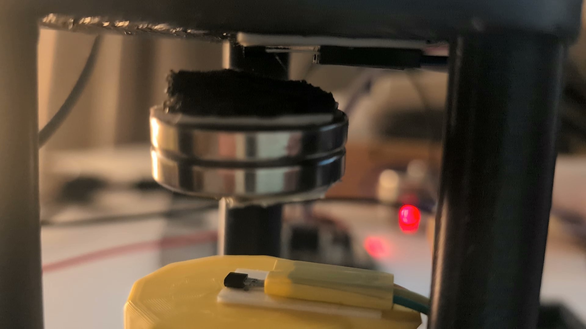
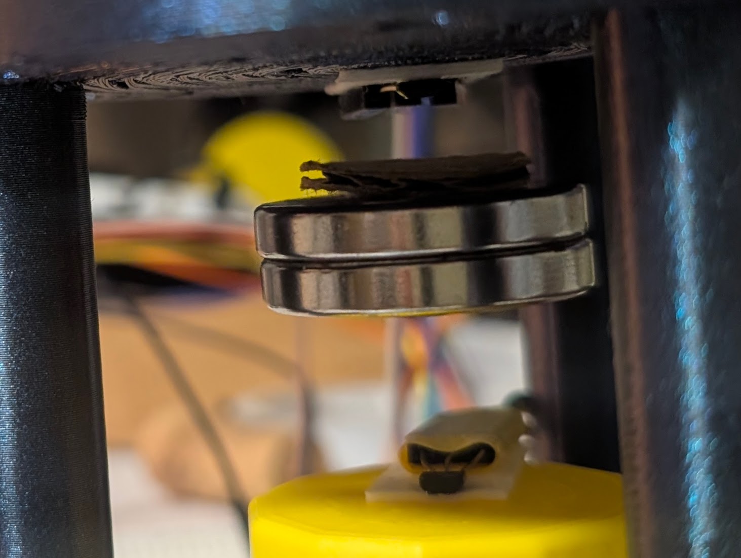
The permanent magnet.
This one is easy. I bought a pack of neodynium magnets years ago to upgrade our collection of things stuck to the refridgerator and used a couple of those. Here’s a closeup of the permanent magnet. I stuck some cardboard onto it so soften the impact when it collides with the sensors.
The electromagnet.
There are a lot more options here. I initially tried the cheapest electromagnet I could get on Amazon and it never felt like it had enough juice to get anything flying. Maybe if I tuned the system perfectly and kept the levitating magnet very close it could have worked but I wasn’t having any luck and started experimenting with larger magnets.
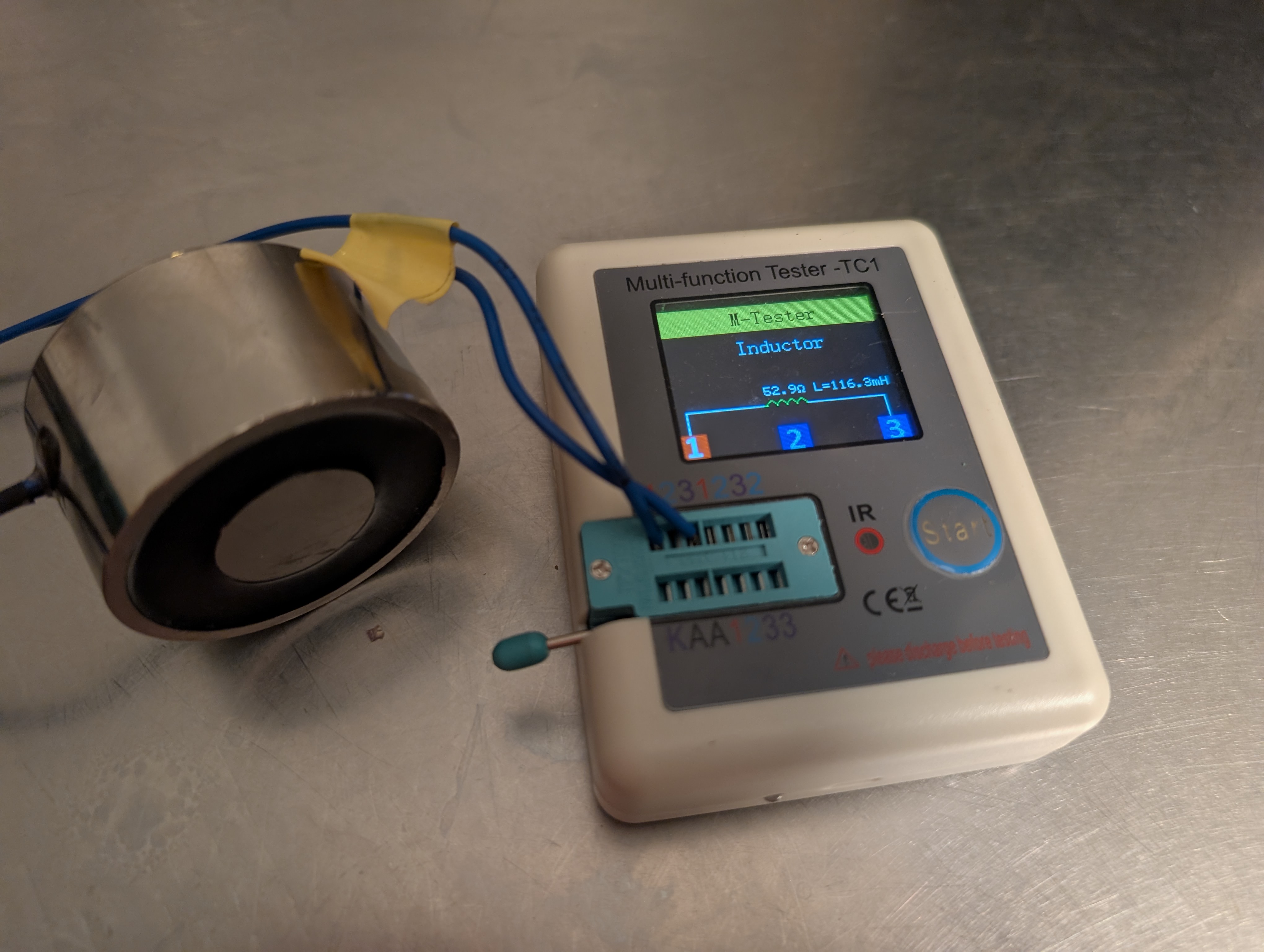
Option #1 – Large iron core magnet
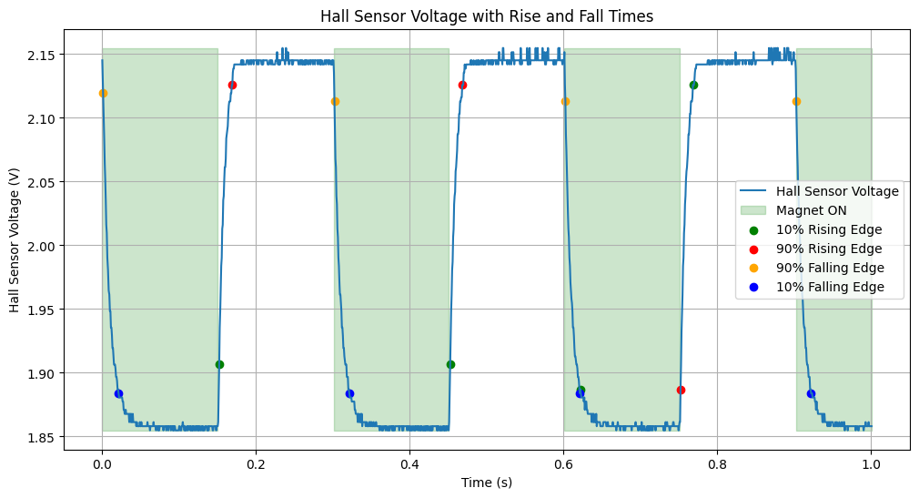
The most powerful magnet I tried had an iron core and was measured at 116.3mH. This could pull anything but I was having trouble tuning the PID loop with it.
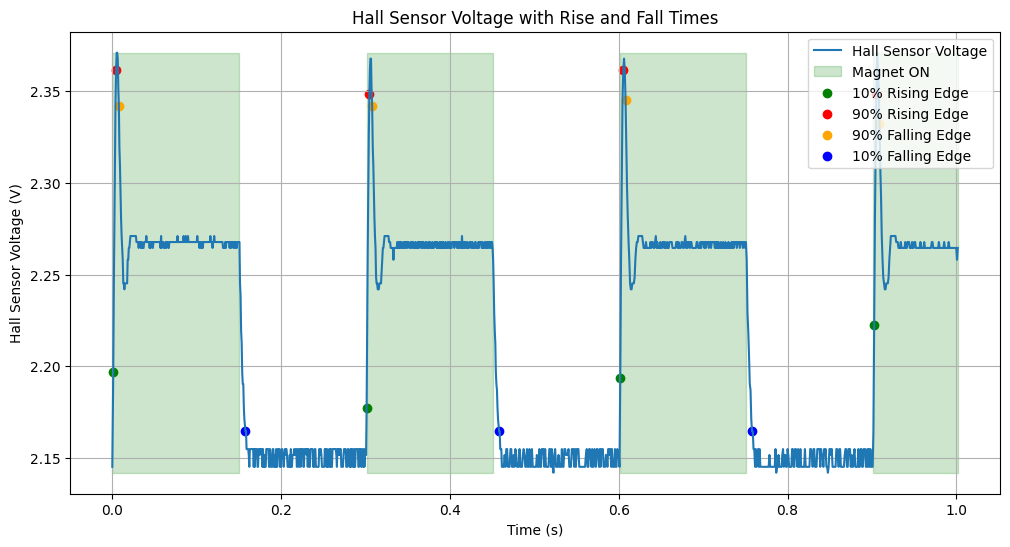
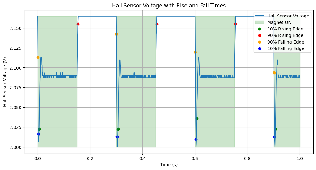
Perhaps its switching speed is too slow? To measure switching spped I wrote a script on my raspberry pi to flip the magnet on/off in one thread while a seperate thread records readings from a Hall Effect sensor very close to the magnet. Here are the results for the big magnet:
Option #2 – Homemade magnet
I suspected I could build a magnet with faster switching times that’s still quite powerful by wrapping magnet wire around a ferrite core. It took a long time wrapping that wire and I only got 26mH out of it.
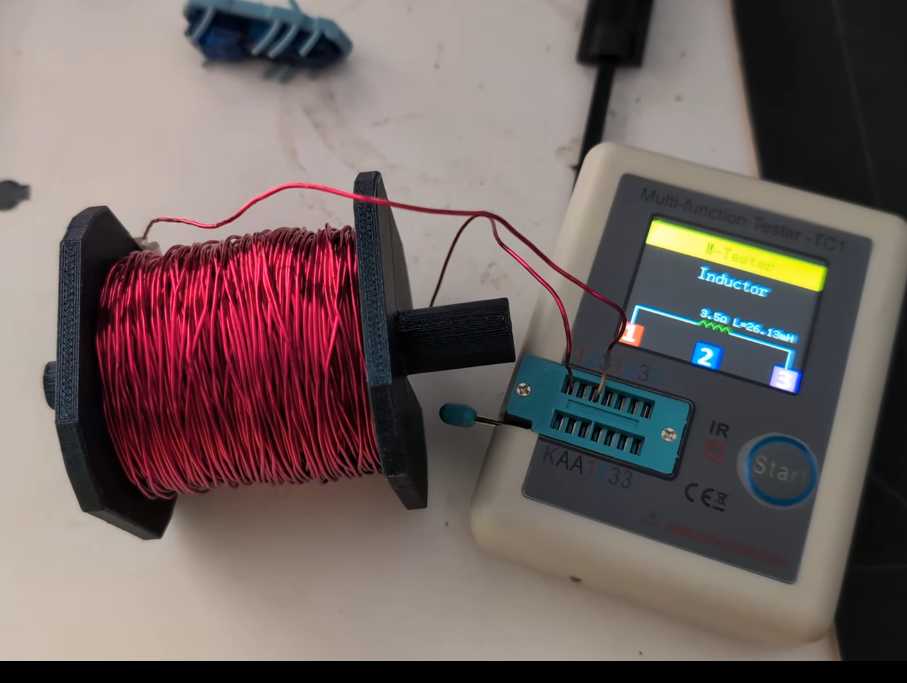
This magnet would get very hot if I played with it for too long. The 3D printed case would soften up and start to melt. There was loud coil whine. The switching speed was very fast but the magnetic field was complicated.
Option #3 (selected) – Air core solenoid
Electromagnets are useful for controlling water flow. There’s a solenoid valve in my espresso machine. I bought a reasonably large solenoid on Alibaba.
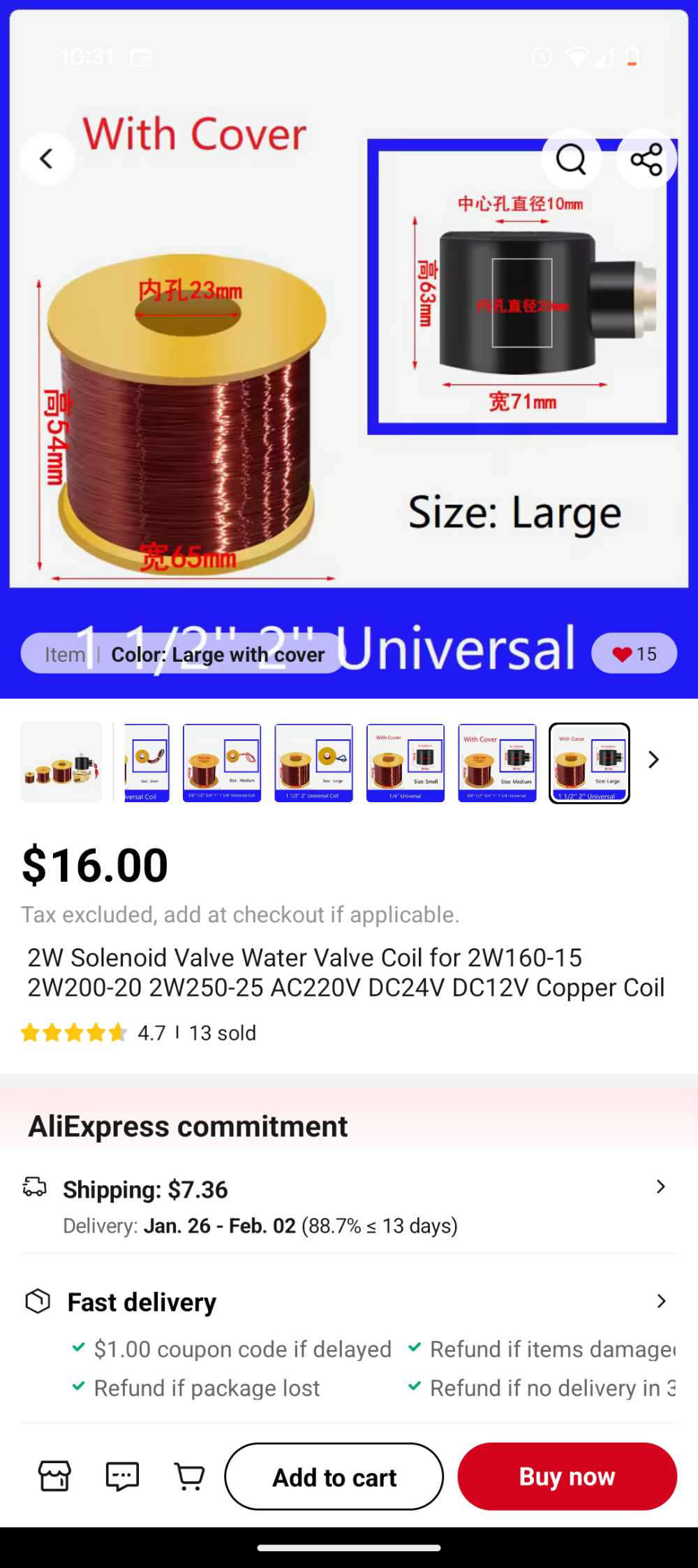
It only measured 9.72mH but that was plenty for my experiment.
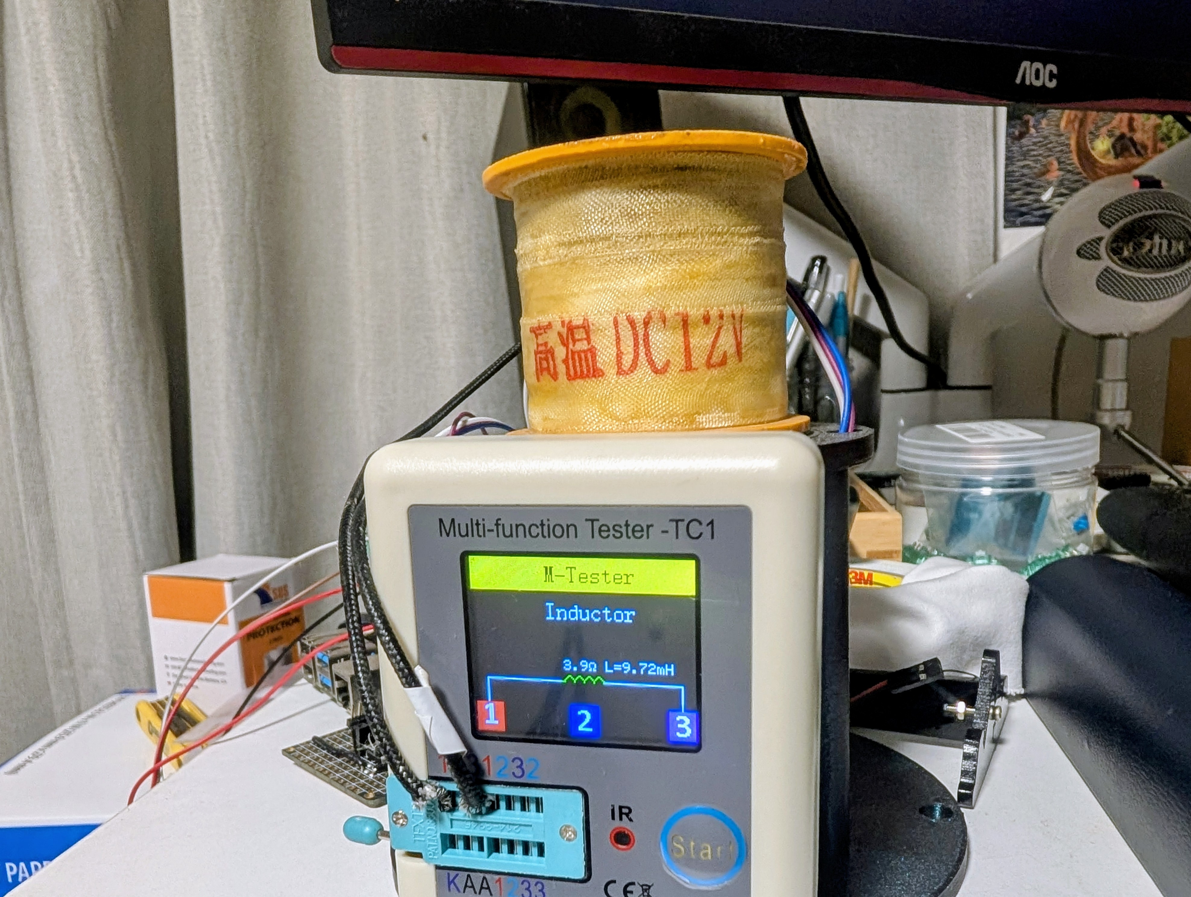
The air core magnet switches very fast:
The Power Supply
The raspberry pi only outputs logic voltage of 3.3V. I need more to power these big magnets. The way to solve this is for the pi to switch a MOSFET which in turn drives current to the magnet. I tried a 9V battery at first. That did not work. 9V batteries have very high internal resistance and can not supply much current. I tried a little RC car power supply also without much luck.
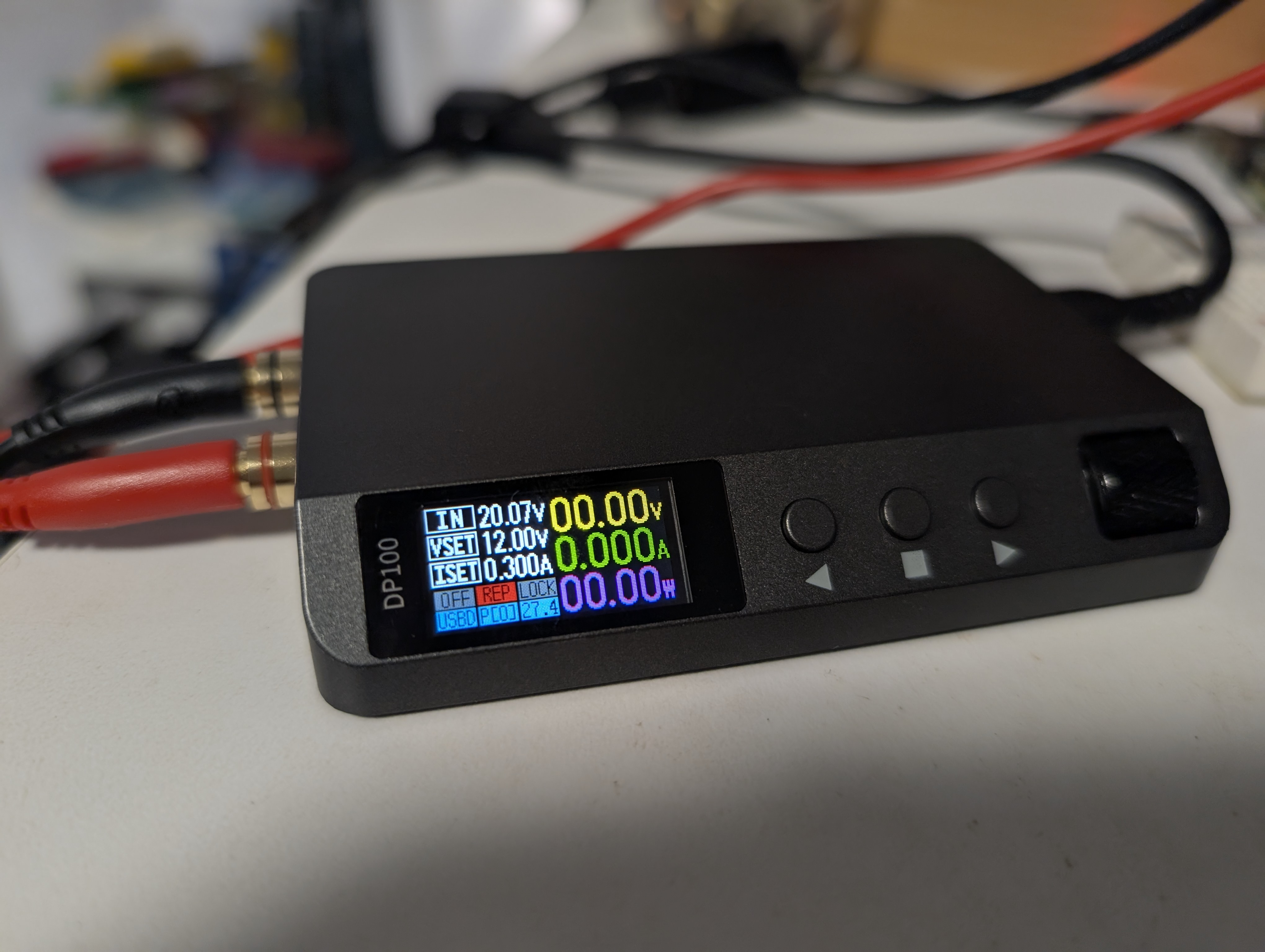
The eventual champion of the power supply bracket was the DP100. I really like this thing and have been using it for all kinds of stuff since buying it for this project.
Sensors
To measure the distance between the permanent magnet and the electromagnet I used a Hall Effect sensor placed underneath the permanent magnet. Placing the Hall Effect sensor far from the electromagnet greatly simplifes this project because, since magnetic field is inverse to the square of the distance, it means that the sensor will primarily measure the field from the permanent magnet rather than a combined field that includes both magnets. Here it is under the magnet: